Maps & fiber plant
Map your entire outside plant — fiber cables, closures, ODBs and ONUs — on Xelynx Maps, manage core connectivity inside every box, and let built-in AI predict where a fiber cut has occurred.
Overview
Xelynx has developed a way for companies to manage and monitor their critical infrastructure (fiber cables, ODBs, ONUs, etc.) and built AI into reporting a lot of detail from it — AI can now predict the area where there is a fiber cut. A lot of R&D has gone into this, and the result is a very intuitive way to do all of it.
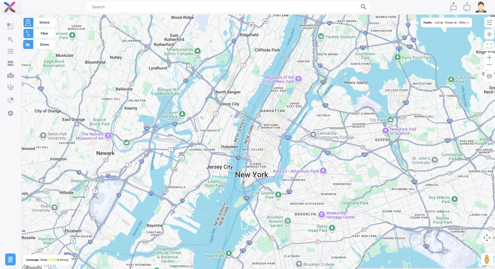
A few things work differently on Xelynx Maps. For example, the search bar on top actually searches on the map.
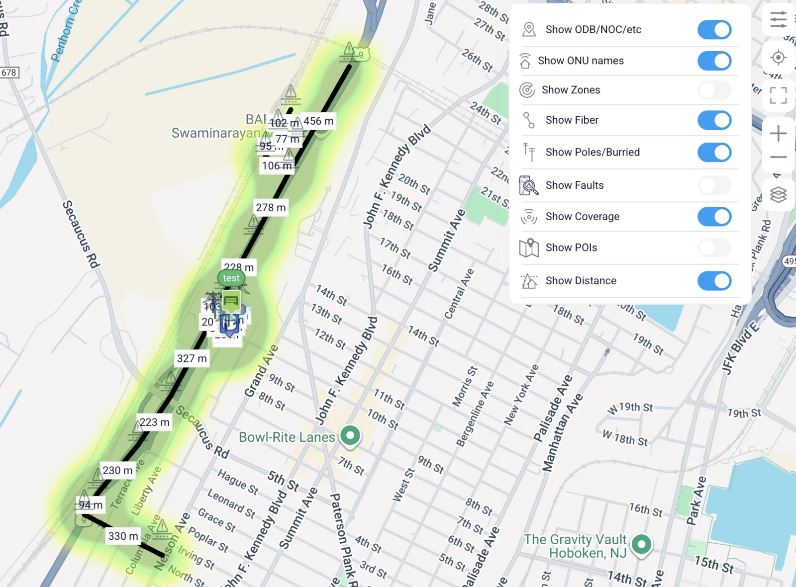
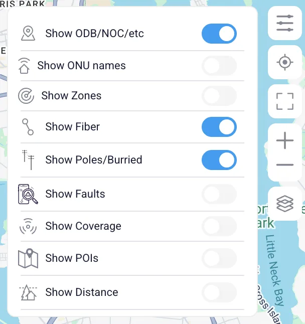
The top-right menu controls which layers are drawn on the map:
- Show ODB/NOC/etc: shows and hides ODBs and NOCs/POPs etc. on Xelynx Maps.
- Show ONU names: shows/hides the names of all ONUs; each ONU's status is reflected in the background color of its name.
- Show Zones: shows/hides zones created on Xelynx Maps.
- Show Fiber: shows/hides fiber optics on Xelynx Maps.
- Show Poles/Buried: shows/hides poles and contours.
- Show Faults: shows/hides faults. AI parses all available data and predicts the infrastructure where there is a fiber cut.
- Show Coverage: shows/hides the coverage of your network.
- Show POIs: shows/hides points of interest on the map.
- Show Distance: shows/hides the distance of fiber between deployed elements.
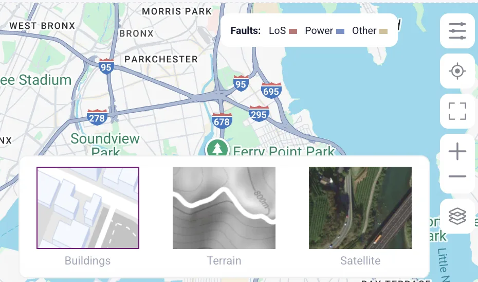
Map's terrain: you can switch between multiple terrain types available on Xelynx Maps.
Fiber elements: a list of the available fiber elements you can deploy as your fiber network infrastructure.
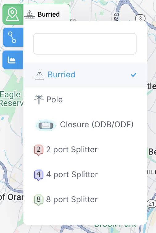
Optical fiber cable: you can select optical fiber cables with different numbers of cores, differentiated by their color.

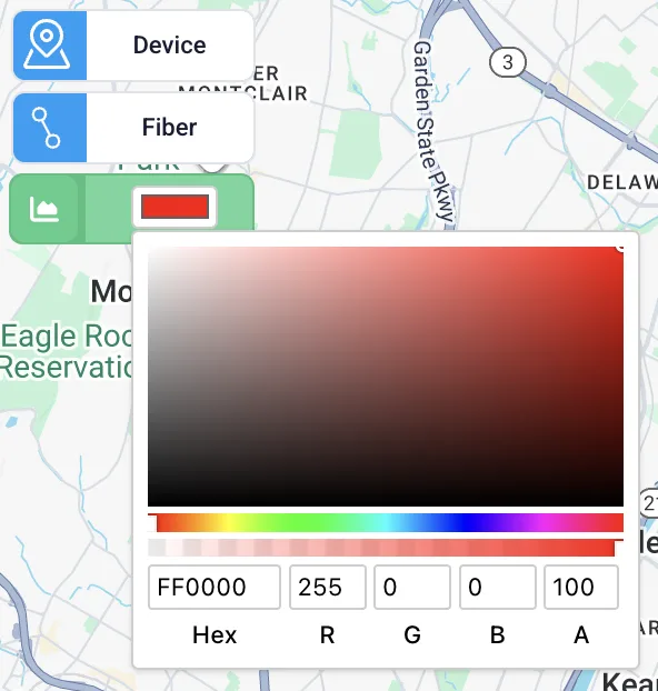
Zones: you can select a color for the zone you are about to create, which makes it easy to distinguish between different zones. A name can be assigned to the zone from its settings.
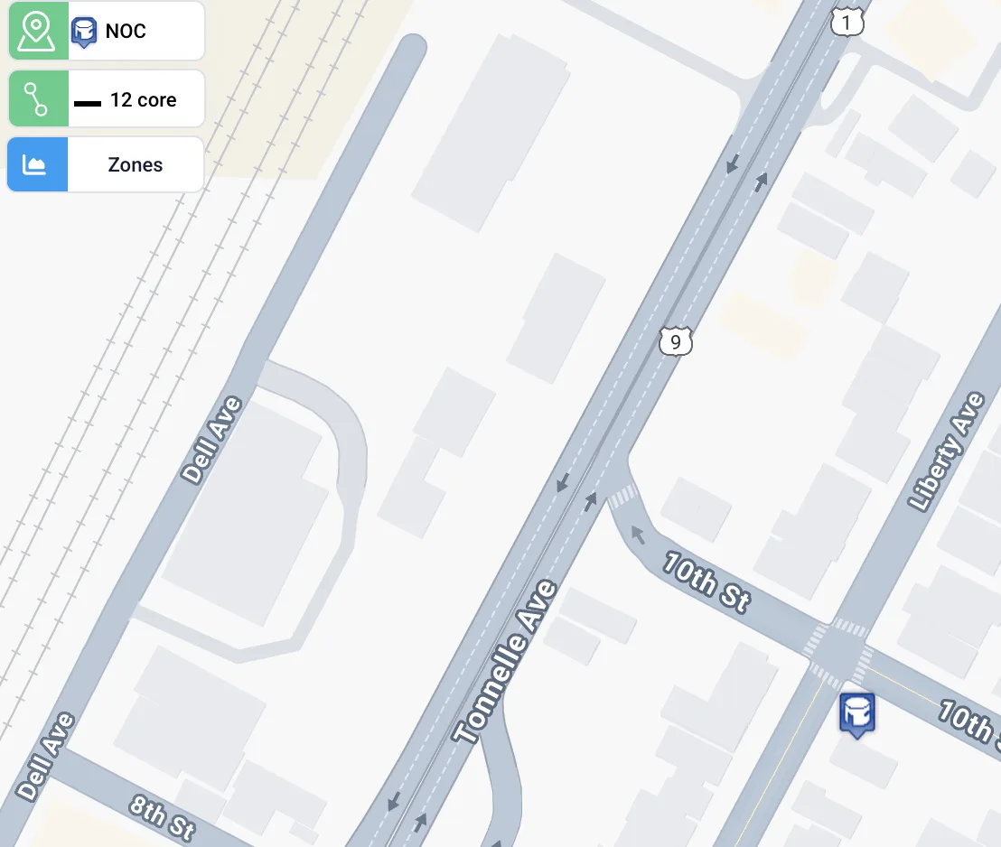
Placing infrastructure elements on the map
First, select the element (NOC, POP, closure box, ODB, etc.) from the menu on the top left. Then select the fiber from the menu below it, and click on the map where you want to place it.
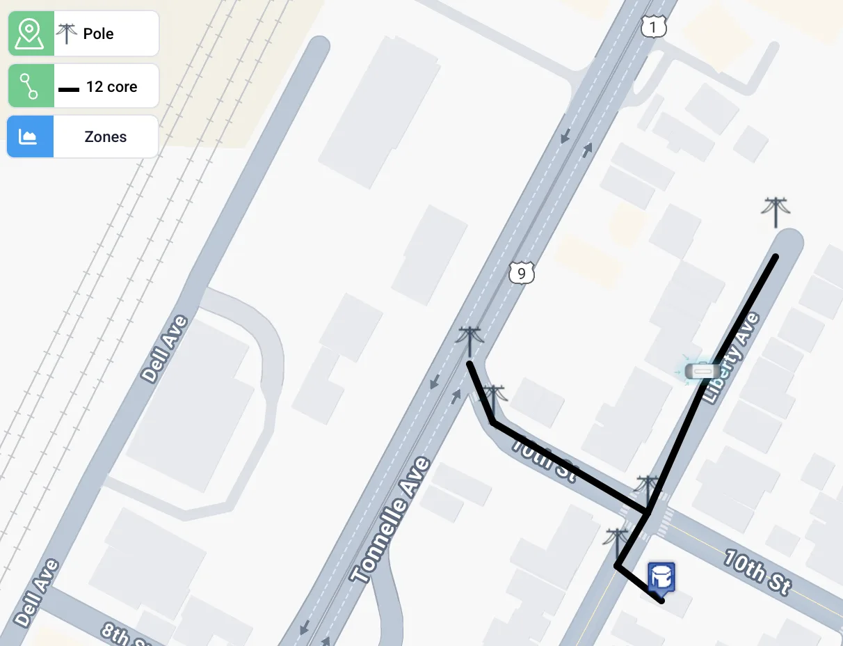
Connecting elements with fiber
Select the element (NOC, POP, closure box, ODB, etc.) from the menu on the top left, then select the fiber from the menu below it. Click on the first element on the map — if it does not exist yet, a new one is created. Click on the second element — again, a new one is created if it does not exist — and both elements are connected with the fiber you selected.
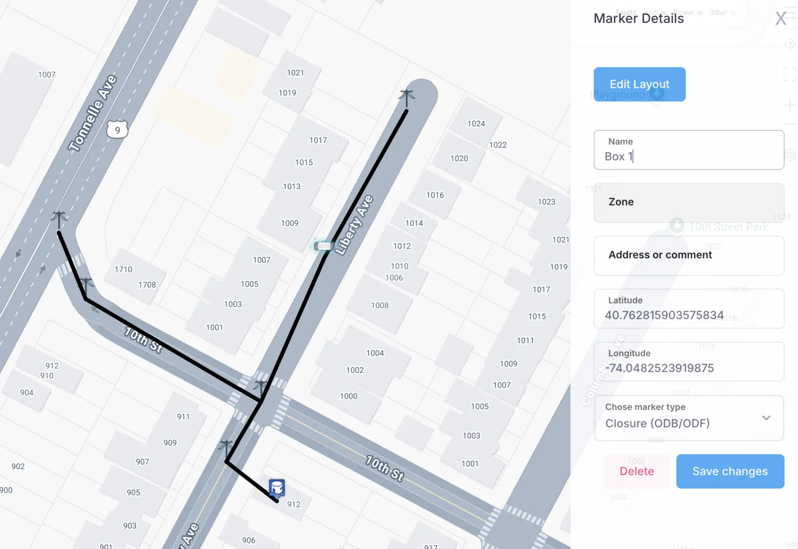
Setting and getting element information
To set or get information about an element, double-click on it and a menu will open from the left side.
Deleting an element
You can delete an element by right-clicking on it, or from the menu that opens when you double-click on it.
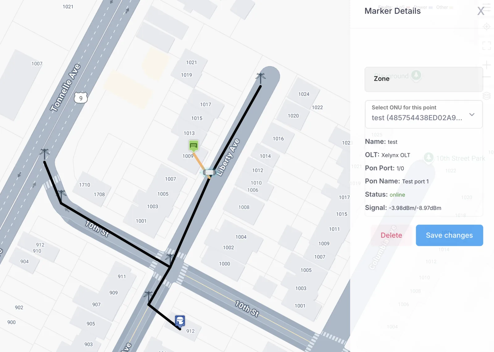
Placing an ONU
Select the ONU marker from the top-left menu, select the fiber you have used to connect it, and place the marker on the map.
Double-click on the ONU marker, select the corresponding ONU from the dropdown list, and save it.
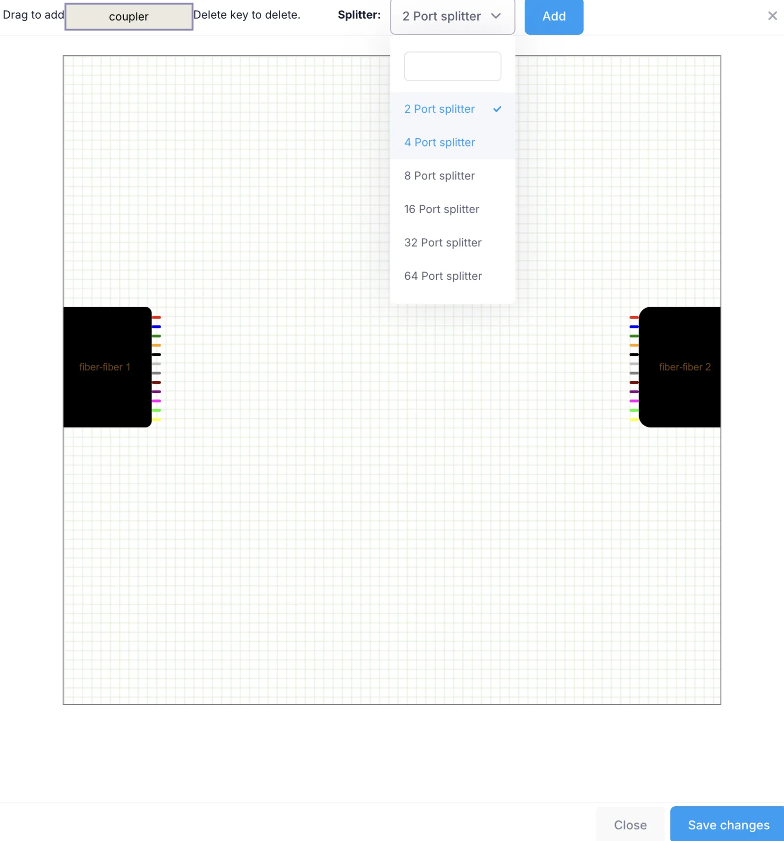
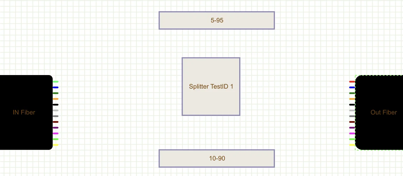
Core connectivity inside a closure box or ODB
Click Edit Layout in the menu that opens when you double-click on the element. The following screen will come up.
You can drag and drop a coupler, or click the Add button to add the selected splitter.
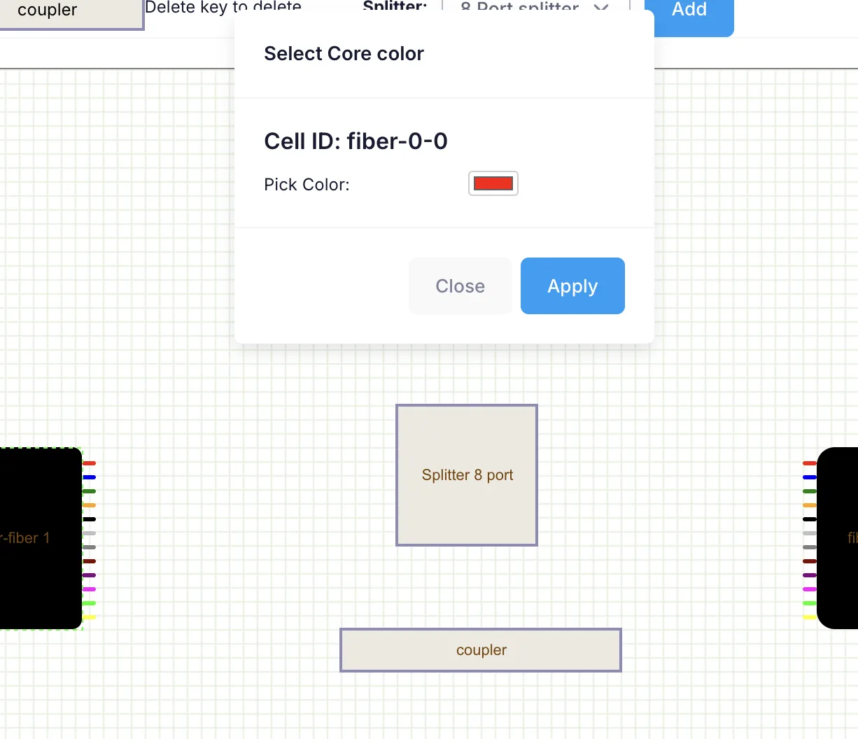
Setting core colors
To change the color of a core, click on the core and a pop-up will come up. You can select any color that matches the exact color of the physical core.
Naming fibers, closures and ODBs
To change the name of an item, click on the item's label and set the name to your liking.
Making core connections
Drag from a core to the point you want to link it to. You can set a label on each connection for future reference.
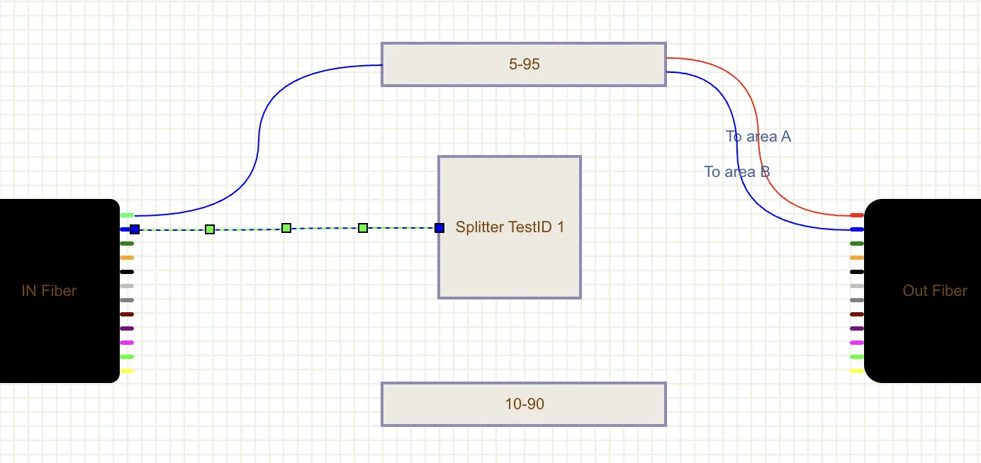
Click Save changes to save the layout to the database.
Details of fiber, markers, coverage and ONU names
These details are displayed on the map when the corresponding options are enabled in the top-right menu.